Use this guide to replace a cracked or shattered iPhone SE screen by replacing the display assembly. To simplify the repair process, this assembly includes the pre-assembled front-facing camera assembly, earpiece speaker, and EMI shield.
You only need to remove the old display; to use fingerprint unlock, you’ll also need to remove the home button assembly and attach it to the new display.
You can also use this guide to replace the front panel assembly cable bracket.
Step 1:Pentalobe Screws
")
Before disassembling your iPhone, discharge the battery below 25%. A charged lithium-ion battery can catch fire or even explode if accidentally punctured.
Power off your iPhone before beginning disassembly.
Remove the two 3.9 mm Pentalobe screws from either side of the Lightning connector.
Step 2: Tape the broken screen
")
If your iPhone’s display is cracked, prevent further cracking by taping the screen with clear tape to prevent damage.
Apply clear tape to the iPhone’s display, covering as much of the display as possible.
This will help contain screen glass and maintain structural integrity when prying and lifting the display.
Wear safety glasses during the repair to protect your eyes from flying glass.
Step 3:Display Separation Precautions

In the next few steps, you’ll need to separate the display from the phone. The display consists of a glass screen and metal clips.
Whichever tool you use, make sure you pull up the entire display.
If the glass begins to separate from the plastic, as shown in the first image, insert a spudger between the plastic frame and the metal body to pry up the rear display clips.
If you’re reassembling the phone, you’ll need to apply a thin layer of adhesive to help seal the phone.
Step 4:Manual Opening Procedure
")
The screen is secured to the rear case with clips, and several ribbon cables connect the screen and the rest of the phone. Your goal is to free the clips and open the phone enough to disconnect the cables. Work slowly and carefully to avoid damaging the cables.
Make sure the suction cup remains firmly attached to the front panel assembly near the home button.
While holding the iPhone in place with one hand, use your other hand to gently separate the iPhone from the home button at the bottom edge of the front panel.
While pulling with the suction cup, use a plastic opening tool to gently pry up along the edge of the rear case to separate the screen from the rest of the phone.
Step 5:Removing the Touch ID cable bracket
")
Open the screen slightly enough to reveal the metal bracket covering the home button cable.
Be careful not to open the screen too far from the phone, as some cables are still connecting it. Excessive separation can damage the home button cable or its connector. Keep the cable loose—if it’s taut, it’s too far apart.
Only the original home button assembly will work with Touch ID. If you rip the cable, installing a new home button will only restore the home button functionality, but will lose the Touch ID functionality.
Use a spudger to push the retaining clip, then remove it with tweezers.
Step 6:Open the phone
")
Once the connector is disconnected, pull the bottom of the home button away from the rear case, using the top of the phone as a pivot.
Allow the display to stand upright at a 90-degree angle. Keep it in this position throughout your repair.
Use a rubber band to secure the display in place as shown in the third image. This will prevent damage to the display cables during the repair.
If necessary, use a handy, heavy object, such as an unopened can, to secure the display.
Step 7
")
Remove the following screws securing the front panel assembly cable bracket to the logic board:
Two 1.7 mm Phillips #000 screws
One 1.2 mm Phillips #000 screw
One 1.3 mm Phillips #000 screw
It is very important to keep track of your screw positions in this step for reassembly. Accidentally using the 1.3 mm or 1.7 mm screw in the right bottom hole will severely damage the logic board and prevent it from booting properly.
Step 8
")
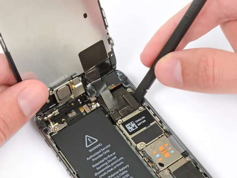
Please pay special attention to this step. Disconnect only the cable from its socket; do not pry it off the logic board.
Use a plastic opening tool to disconnect the front camera and sensor cables from their sockets and separate them from the logic board.
Use a plastic opening tool to disconnect the sensor cable connector and separate it from the logic board.
Step 9
")
The display assembly can now be completely separated from the rear case.
During reassembly, if you have new adhesive strips, remove them first before reapplying them.